Detailed analysis of the electric and magnetic fields produced by the human heart requires a convenient and mathematically consistent coordinate system. Several different rectangular and spherical coordinate systems are being used in clinical electrocardiography, but none fulfill these requirements. In clinical electrocardiology the right-handed rectangular coordinate system standardized in 1967 by the American Heart Association (AHA; American Heart Association, 1967) has been most frequently used. However, this coordinate system is a result of historical development and is not necessarily the rational choice from all possible alternatives.
 The basis for the AHA coordinate system arises from the basic research performed by Willem Einthoven. Einthoven defined the positive x axis as oriented from the right to the left side of the patient (which actually means from left to right when viewed from an observer, as traditionally defined in physics). Because the electric heart vector is typically directed to the left, back, and down, Einthoven chose the y axis to point down so that the main deflection of the QRS complex is positive. Einthoven investigated the ECG signal only in the frontal plane and therefore did not need the z coordinate.
 When constructing his vectorcardiographic system, Frank decided to accept the x and y directions defined by Einthoven and defined the z coordinate to point to the back in order to have a right-handed coordinate system. This coordinate system is the one standardized by AHA.
 The coordinate system of AHA includes the following shortcomings:
Relative to the natural observation planes of the patient (i.e., the frontal plane observed from the front, the sagittal plane observed from left, and the transverse plane observed from above), only the sagittal plane is observed from the positive side.
The spherical coordinate system, fixed to this coordinate system with the generally accepted axes, results in an unfamiliar orientation.
 Additionally, Einthoven's attempt to obtain a positive deflection of the electric y signal results in a negative deflection in the magnetic signal.
 For these reasons Malmivuo developed a consistent coordinate system for electrocardiology, which avoids the aforementioned drawbacks (Malmivuo, 1976; Malmivuo et al., 1977).
 | I: | 0° | to | 90° |
 | II: | 90° | to | 180° |
 | III: | 180° | to | 270° |
 | IV: | 270° | to | 360° |
A.3 ALIGNMENT OF THE RECTANGULAR COORDINATE SYSTEM WITH THE BODY
The origin of the coordinate system should be in the geometric center of the heart. The orientation of the coordinate system with respect to the body is of little mathematical consequence but of great practical importance.
 It is convenient to align the rectangular coordinate axes with the body axes (i.e., sagittal, transverse, and longitudinal axes). This means that the coordinate planes correspond to the frontal, left sagittal, and transverse planes. In order that the planes be viewed from their positive side and that these views be the same as those used in clinical vector electrocardiography, the positive directions of the x, y, and z axes are chosen to be anterior, left, and superior, respectively. The consistent rectangular coordinate system is illustrated in Figure A.1. The three coordinate planes including their four quadrants and the convention for measuring the angles are illustrated in Figure A.2.
 Note that selection of the positive directions of the axes in the above order provides the most practical orientation for the illustrative spherical coordinates (see Figure A.3B).
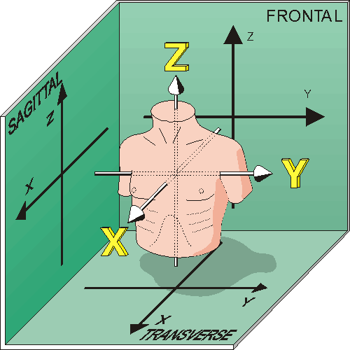
Fig. A.1 The consistent rectangular coordinate system.
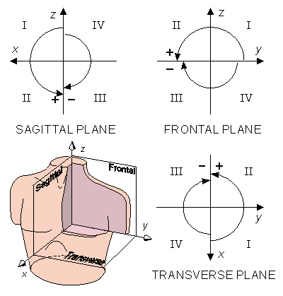
Fig. A.2 Display of the three standard projections in the consistent rectangular coordinate system. The arcs indicate the positive and negative deviation of the angles in each coordinate plane.
  | |
  | (A.1) |
  |
A.4.2 Illustrative Spherical Coordinate System
If the behavior of the electric or the magnetic heart vector is displayed in the mathematically consistent spherical polar coordinate system the direction of increasing values on the vertical axis is inconveniently downward. Therefore to avoid this deficiency it is preferably to use the same spherical coordinate system which is familiar in the geographical projection of the Earth. This coordinate system differs from the mathematically consistent coordinate system in the following way, that instead of the colatitude angle, the latitude angle is used. The latter is measured from the xy plane. In this coordinate system the spherical coordinates are related to the rectangular coordinates by the following equations:
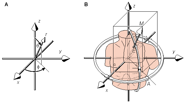
 The radius vector is described by the symbol r. The angles q and f are called colatitude and longitude, respectively. The angle q is also called polar angle because it is an angle dimensioned from the pole (i.e. z axis). These requirements for rectangular and spherical polar coordinates are based on existing mathematical conventions. This mathematically consistent coordinate system is illustrated in Figure A.3A.


(A.2) 

 In the illustrative spherical coordinate system, the vector magnitude is represented by the symbol M (being the same as the radius vector r in the spherical polar coordinate system). The angles E and A are called the elevation and azimuth, respectively. This coordinate system is illustrated in Figure A.3B. (Note, that when the angles elevation and azimuth are those used in connection with the AHA coordinate system, they are represented by symbols V and H and they differ from those of the consistent system introduced in this chapter.)
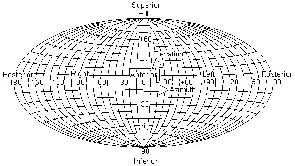
 The angles elevation and azimuth correspond exactly to the latitude and longitude angles, respectively, used in geography. Therefore, ordinary (and familiar) geographic map projection techniques can be immediately applied to maps of electric potential and magnetic field over the entire torso surface, as described in Figure A.4.


