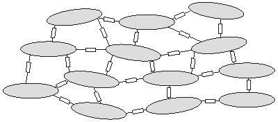
Many investigations in electrophysiology involve preparations that contain multiple cells. Examples include the nerve bundle, which consists of several thousand myelinated fibers; striated whole muscle, which may contain several thousand individual fibers; the heart, which has on the order of 1010 cells; and the brain, which also has about 1010 cells. In modeling the electric behavior of such preparations, the discrete cellular structure may be important (Spach, 1983). On the other hand, macroscopic (averaged) fields may adequately describe the phenomena of interest. In the latter case it is possible to replace the discrete structure with an averaged continuum that represents a considerable simplification. The goal of this chapter is to formulate a continuum representation of multicellular systems and then to explore its electric properties.
 - -   i = i =    o = Im o = Im | (9.3) |
| where | Im | = transmembrane current per unit volume [µA/cm3]. |
 In retrospect, the weakness in the bidomain model is that all fields are considered to be spatially averaged, with a consequent loss in resolution. On the other hand, the behavior of all fields is expressed by the differential Equations 9.1-9.3 which permits the use of mathematical approaches available in the literature on mathematical physics.
  | (9.4) |
where the space constant, l, is defined as
and has the dimension [cm]. This is the same as in Equation 3.48.
If Equation 9.7 is applied at either end of the preparation (x = ± l /2), where
Substituting Equation 9.6 into Equation 9.8 permits evaluation of Ka as
Consequently, substituting Equation 9.9 into Equation 9.6 results in


(9.5)  In Equation 9.4, and in the following equations of this chapter, Vm describes the membrane potential relative to the resting potential. Consequently Vm corresponds to the V' of Chapter 3. Since, under resting conditions, there are no currents or signals (though there is a transmembrane voltage), interest is usually confined entirely to the deviations from the resting condition, and all reference to the resting potential ignored. The literature will be found to refer to the potential difference from rest without explicitly stating this to be the case, because it has become so generally recognized. For this more advanced chapter we have adopted this common practice and have refrained from including the prime symbol with Vm.
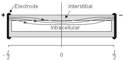
 For the preparation in Figure 9.2, we anticipate a current of Ia to enter the interstitial space at the left-hand edge (x = - l /2), and as it proceeds to the right, a portion crosses the membrane to flow into the intracellular space. The process is reversed in the right half of the fiber, as a consequence of symmetry. The boundary condition of Ii = 0 at x = ± l /2 depends on the ends being sealed and the membrane area at the ends being a very small fraction of the total area. The argument is that although current may cross the end membranes, the relative area is so small that the relative current must likewise be very small (and negligible); this argument is supported by analytical studies (Weidmann, 1952). Since the transmembrane voltage is simply the transmembrane current per unit length times the membrane resistance times unit length (i.e., Vm = imrm), the antisymmetric (i.e., equal but opposite) condition expected for im must also be satisfied by Vm. Since the solution to the differential equation of 9.4 is the sum of hyperbolic sine and cosine functions, only the former has the correct behavior, and the solution to Equation 9.4 is necessarily:
 Vm = Ka sinh(x/l)
(9.6)
where Ka = a constant related to the strength of the supplied current, Ia.  We found earlier for the axial currents inside and outside the axon, in Equation 3.41 that


(9.7a)


(9.7b)  Fi /
Fi / x = 0 and where Io = Ia, we get


(9.8)


(9.9)


(9.10)  We are interested in examining the intracellular and interstitial current behavior over the length of the fiber. The intracellular and interstitial currents are found by substituting Equation 9.10 into Equations 9.7a,b, while noting that Vm = Fi - Fo and that the intracellular and interstitial currents are constrained by the requirement that Ii + Io = Ia for all x due to conservation of current. The result is that


(9.11)


(9.12)  The intracellular and interstitial currents described by Equations 9.11 and 9.12 are plotted in Figure 9.4 for the case that l = 20l and where ri = ro/2. An important feature is that although the total current is applied to the interstitial space, a portion crosses the fiber membrane to flow in the intracellular space (a phenomenon described by current redistribution). We note that this redistribution of current from the interstitial to intracellular space takes place over an axial extent of several lambda. One can conclude that if the fiber length, expressed in lambdas, is say greater than 10, then in the central region, essentially complete redistribution has taken place. In this region, current-voltage relations appear as if the membrane were absent. Indeed, Vm
  0 and intracellular and interstitial currents are essentially axial and constant.
 The total impedance presented to the electrodes by the fiber can be evaluated by dividing the applied voltage Va[Fo(-l /2) - Fo(l/2)] by the total current Ia. The value of Va can be found by integrating IoRo from x = -l /2 to x = l /2 using Equation 9.12. The result is that this impedance Z is


(9.13)  If l
If l  l and if ri and ro are assumed to be of the same order of magnitude, then the second term in the brackets of Equation 9.13 can be neglected relative to the first and the load is essentially that expected if the membrane were absent (a single domain resistance found from the parallel contribution of ro and ri). And if l
  l , then tanh(l/2l)
  l/2l and Z = rol, reflecting the absence of any significant current redistribution; only the interstitial space supplies a current flow path. When neither inequality holds, Z reflects some intermediate degree of current redistribution.
 The example considered here is a simple illustration of the bidomain model and is included for two reasons. First, it is a one-dimensional problem and hence mathematically simple. Second, as we have noted, the preparation considered is, in fact, a continuum. Thus while cardiac muscle was approximated as a continuum and hence described by a bidomain, in this case a continuum is not just a simplifying assumption but, in fact, a valid description of the tissue.
 Although we have introduced the additional simplification of subthreshold and steady-state conditions, the basic idea of current redistribution between intracellular and interstitial space should apply under less restrictive situations. It seems trivial to point out that whenever a multicellular region is studied, its separate intracellular and interstitial behavior needs to be considered in view of a possible discontinuity across the membrane (namely Vm). This is true whether the fibers are considered to be discrete or continuous..
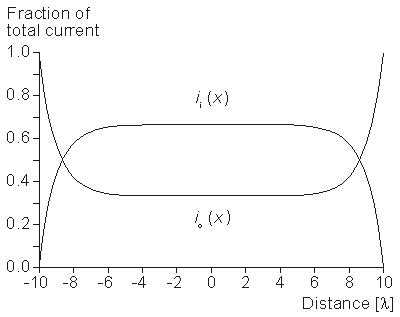
- Figure 9.4. Distribution of intracellular axial current ii(x) and interstitial axial current io(x) for the fiber described in Figure 9.2. The total length is 20l and ri /ro = 1/2. Note that the steady-state conditions which apply for -7l < x < 7l , approximately suggest
 3 l as an extent needed for current redistribution.


 8.5 nm) through which it passes, plus the gap between membranes (3 nm) - or around 20 nm total. This length is very short in contrast with the length of a cell itself, since the ratio is roughly 20

 ,
,  ,
,  ,
,  ,
,  ,
, 

 ,
,  ,
,  ,
, 


 0 is
0 is

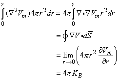
 0 is correct. This condition is introduced by integrating each term in Equation 9.25 through a spherical volume of radius r